Agilex™ 9 Direct RF SoC Evaluation Made Easy with MATLAB-Based Cockpit GUI
July 1, 2026
Article
Accelerate RF System Evaluation Without Complex Software Development
Developing high-performance RF systems requires extensive hardware setup, calibration, synchronization, and signal verification. For building Software Defined Radio (SDR), radar, wireless infrastructure, aerospace, or defense applications, these tasks can significantly increase development time before application testing even begins.
To simplify this process, iWave provides a MATLAB-based Cockpit GUI that allows engineers to configure, calibrate ADC & DAC channels, perform latency & phase alignment, and monitor RF performance on the Agilex 9 Direct RF platform without developing custom control software.
Built around the Agilex™ 9 AGRW014 Direct RF SoC FPGA System on Module and hosted on the iG-G67P PCIe Development Platform, the solution combines high-performance RF hardware with a MATLAB-based Cockpit GUI that enables rapid platform evaluation
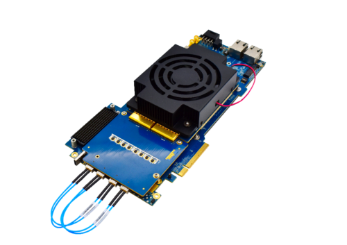
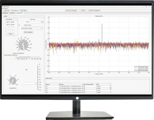
Figure 1: Agilex 9 Direct RF PCIe based Development Platform
Complete Development Platform for RF Evaluation
The Agilex 9 Development platform consists of:
- Agilex 9 AGRW014 Direct RF SoC FPGA SOM
- iG-G67P PCIe Carrier Card
- iWave’s RF Daughter Board
- Integrated RF clock generation solution
- Linux-based software environment
- MATLAB-Based Cockpit GUI
MATLAB-Based Cockpit GUI Overview:
The MATLAB-based Cockpit GUI provides a centralized interface for configuring, controlling, and monitoring the Agilex™ 9 Direct RF platform. Designed to simplify RF evaluation, the GUI enables engineers to quickly set up the hardware, calibrate ADC and DAC channels, synchronize multiple RF channels, and monitor system performance, all from a single interface.
When launched, the GUI automatically detects the connected hardware and displays key system information, including the configured sampling rate and platform status, allowing engineers to begin evaluation with minimal setup.
The Cockpit GUI also provides access to various hardware setup functions including:
- ADC and DAC calibration
- Latency alignment
- Phase alignment
- Signal viewer
- Hardware status monitoring
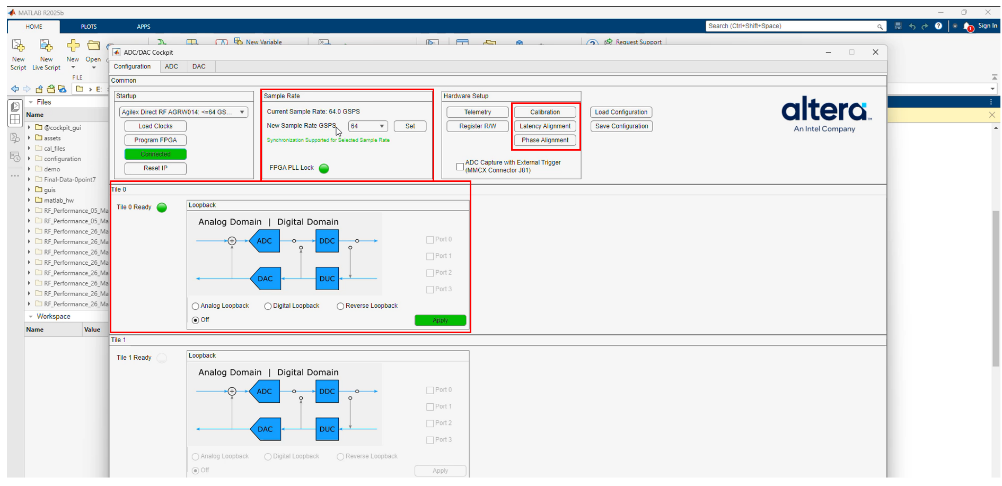
Figure 2: Cockpit GUI
ADC and DAC calibration:
The Cockpit GUI provides dedicated calibration functions for both ADC and DAC channels, helping engineers optimize RF performance with minimal effort.
- ADC Foreground Calibration compensates for variations in the receive path, improving signal acquisition accuracy and channel consistency.
- DAC Foreground Calibration corrects converter characteristics to enhance signal generation and output quality.
- OTP Calibration allows users to apply factory-programmed calibration coefficients, enabling optimized converter performance across supported bandwidth ranges when available.
These calibration tools help ensure reliable and consistent RF performance across the Agilex™ 9 Direct RF platform.
Latency alignment:
The Cockpit GUI simplifies multi-channel synchronization by automatically measuring and aligning latency across ADC and DAC channels.
Using digital loopback mode, the platform calculates round-trip latency and compensates for timing differences between channels. Engineers can also manually fine-tune channel delays and verify synchronization through the integrated Signal Viewer.
This feature is particularly valuable for applications requiring deterministic timing, such as radar, phased-array systems, and Software Defined Radio (SDR)
Phase alignment:
The Cockpit GUI simplifies multi-channel RF synchronization by automatically measuring and compensating for phase differences across ADC and DAC channels. This ensures consistent phase relationships between channels, enabling accurate signal acquisition and coherent signal transmission.
- ADC Phase Alignment synchronizes all receive channels with a reference channel, improving signal accuracy for multi-channel RF processing.
- DAC Phase Alignment compensates for phase differences between transmit channels, enabling coherent signal generation for applications such as phased-array radar, beamforming, and Software Defined Radio (SDR).
Signal Viewer:
The Signal Viewer in the Cockpit GUI provides real-time visualization of the captured RF signals. After configuring the ADC and DAC channels, the generated Frequency from DAC is transmitted through the external loopback path and received by the ADC. The Signal Viewer displays the signal in both time-domain and frequency-domain views, allowing users to verify signal and system performance.
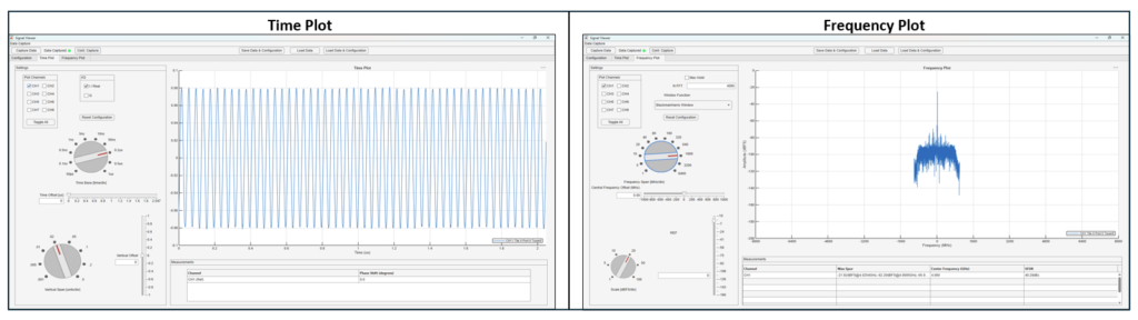
Figure 3: Signal Viewer
Figure 3 shows a successfully captured 4 GHz signal in the frequency-domain view, demonstrating accurate signal generation, acquisition, and processing through the Agilex™ 9 Direct RF platform.
See the Agilex™ 9 Direct RF platform in action by watching the complete demonstration, showcasing RF configuration, calibration, synchronization, and real-time signal visualization using the MATLAB-based Cockpit GUI.
For more information about iWave’s Agilex 9 RF solutions, please contact us at mktg@iwave-global.com.
