Get started with i.MX 8 QM/QP Pico ITX Single Board Computer
Unpacking
Remove the SBC from the box and place it above the ESD free area. Use anti-static pad/mat with proper grounding to place the Development Platform. Also make sure that, below deliverables are received without any physical damage.
Development kit contains:
i.MX 8M QM/QP Pico ITX SBC
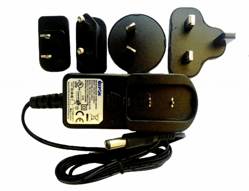
12V, 2A Power Supply
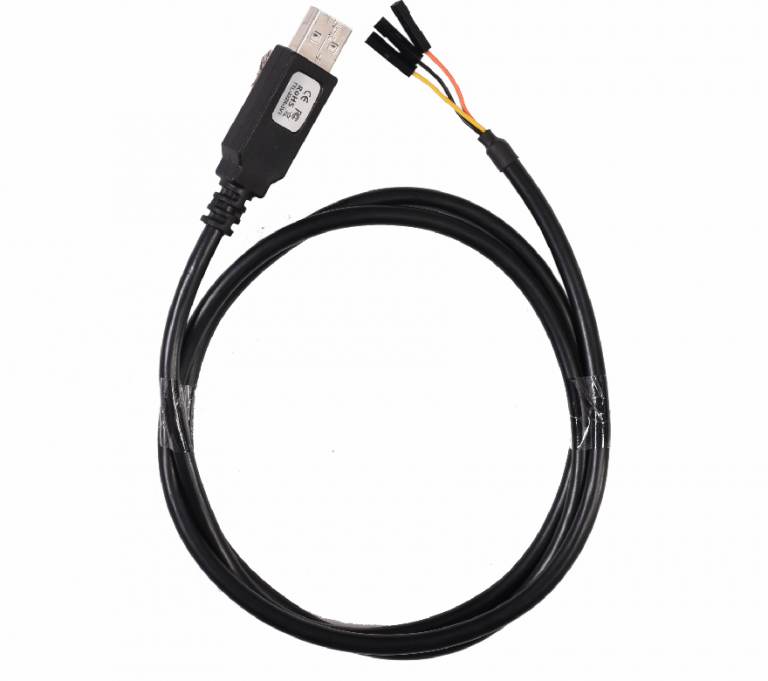
Debug cable (3V3)*
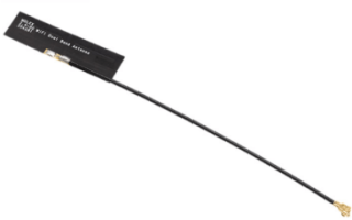
Wi-Fi BT Antenna*
Safety guidelines
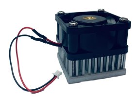
Fan
i.MX 8M QM/QP Pico ITX SBC
Wi-Fi & BT Antenna*
Debug cable
12V,POWER SUPPLY
Fan Sink
* Optional
Safety Guidelines
Environmental Compliance iG-G27S® i.MX 8QM/QP SBC Development Platform is designed by using oHS and REACH compliant components and manufactured on lead-free production process.
ESD Protection This development platform is ESD sensitive. Handle the product only in accordance with the installation instructions given in the manual. Therefore ESD precautions should be taken care during transport and handling. Must use a ESD ground strap or other grounded source before unpacking or handling the hardware.
Product Disposal Check the local regulations for disposal of electronic products before disposing.
Get to know
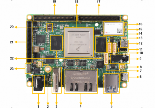
i.MX QM/QP Pico ITX SBC – Top view
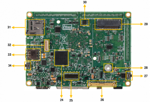
1. Power IN Jack 2. FAN Header 3. HDMI TX Connector 4. Dual Ethernet Jack 5. Dual USB 3.0 Connector 6. USB OTG Connector 7. Line in Header* 8. RTC Header 9. Audio IN/OUT Jack 10. RS232 Header 11. Debug UART Header 12. HDMI RX Connector
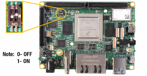
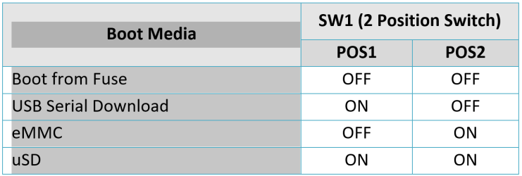
Make sure On-Board Switch (SW1) is set properly as shown below image.
Table 1: Boot Media Switch Settings
Debug Port Setting
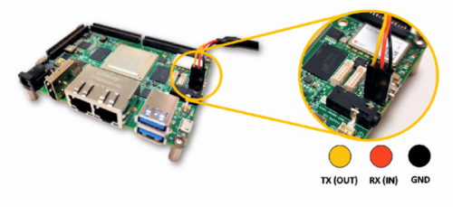
Connect Type A end of TTL-232R-RPI cable to PC and 3pin (100mil) Berg house end of TTL-232R-RPI cable to Expansion Connector (J7) as shown below.
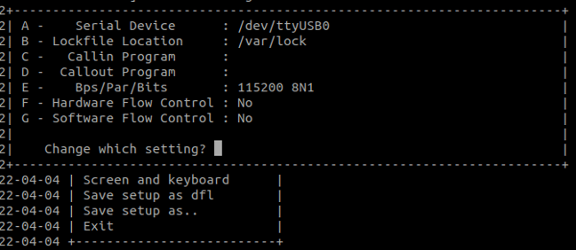
Use one of the terminal application depending on the operating system of the host machine:
On the command prompt of the Linux host machine, run the following command to determine the port number: $ ls /dev/ttyUSB* The smaller number is for Arm® Cortex®-A53 core and the bigger number is for Arm® Cortex ®-M4 core.
Minicom
Use the following commands to install and run the serial communication program (minicom as an example):
DownloadTera Term. After the download, run the installer and then return to this webpage to continue.
Launch Tera Term. The first time it launches, it shows the following dialog. Select the serial option. Assuming your board is plugged in, there should be a COM port automatically populated in the list.
Configure the Serial Port Settings.
Go to Setup –> Serial Port and change the settings as shown below.
Verify that the connection is open. If connected, Tera Term shows something like below in its title bar.
DownloadPuTTY. After the download, run the installer and then return to this webpage to continue.
Launch PuTTY by either double clicking on the executable file you downloaded or from the Start menu, depending on the type of download you selected.
Configure in the window that launches. Select the Serial radio button and ether the COM port number that you determined earlier. Also enter the baud rate, 115200
Click “Open” to open the serial connection. Assuming the board is connected and you entered the correct COM port, the terminal window opens. If the configuration is not correct, puTTY alerts you.
Next step is to Power ON the board.
Powering ON
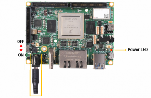
Connect the Power supply plug to the Power connector (J17) of the SBC as shown below and switch ON the power supply. Once power is applied to the SBC, the power LED in the SBC will glow as shown in the below image.
Warning:
Do not try to connect any other Power Supply other than supplied along with iG-G27S® i.MX 8QM/QP SBC
Contact iWave, if power LEDs are not glowing.
Boot screen
User must go through “Software User Guide” and get familiar with software section of iG-G27S® i.MX 8QM/QP SBC
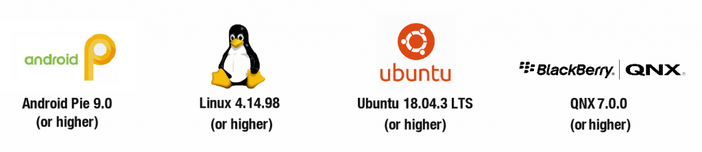
Operating System Support
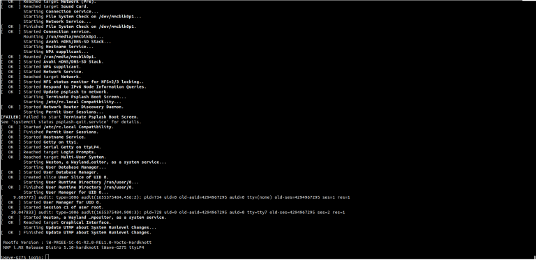
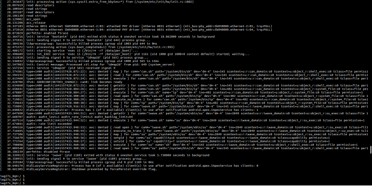
Power is applied to the SBC & once the boot get success, depending upon the supported Operating systems and boot loader on particular Delivery, boot messages being prompted in the terminal window as shown below. Press Enter key in terminal and done with test environment setup on particular delivery.
Command Prompt (Linux)
Command Prompt (Android)
Linux Home Screen
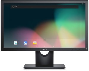
Android Home screen
QNX Home Screen
Ubuntu Home screen
Contact Us
We appreciate you contacting iWave. Our representative will get in touch with you soon!